Provisioning
Provisioning Sequence
The sequence diagram below captures the high level steps that occur for remote provisioning of EKS Anywhere Bare Metal clusters.
sequenceDiagram
    autonumber
    participant admin as Administrator
    participant rafay as Rafay Controller
    box Remote Datacenter
    participant gateway as Gateway
    participant kind as Temporary Kind Cluster
    participant cluster as EKSA Bare Metal Cluster
    end
    note over rafay, gateway: Port 443 Outbound Control Channel
    admin->>rafay: Cluster Spec
    gateway->>rafay: Pull Cluster Spec
    gateway->>kind: Provision kind Cluster
    kind->>cluster: Provision EKSA Cluster
    kind->>cluster: Pivot Management
    gateway->>kind: Destroy kind Cluster
    cluster->>rafay: Ongoing Management
    admin->>rafay: Interact with Remote Cluster
Prerequisites
Ensure to have minimum of one machine in the datacenter (which can act as both control plane and worker node). You can either have one machine or 'n' number of machines where one machine act as a control plane and the other(s) as worker node(s).
Self Service Wizard
The wizard prompts the user to provide critical cluster configuration details organized into logical sections:
- General
- Tinkerbell Datacenter Config
- Tinkerbell Template Config
- Tinkerbell Machine Config
- Controle Plane Config
- Worker Node Groups
- Cluster Network
- Tinkerbell Hardware Config
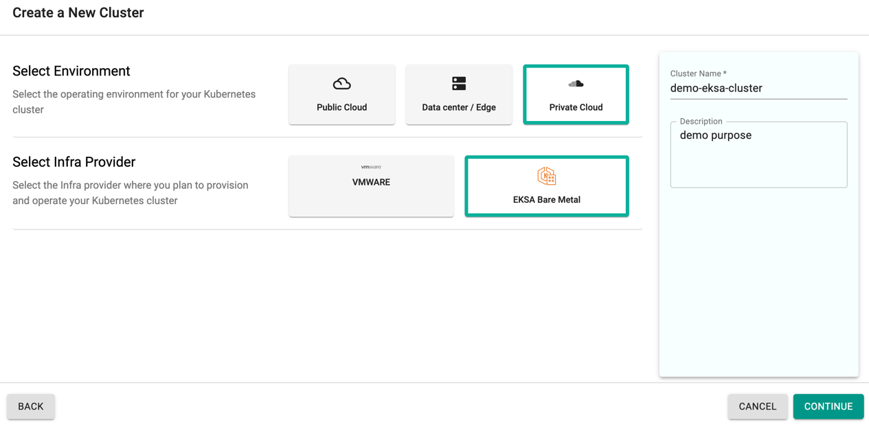
Create Cluster
- Click Clusters on the left panel and the Clusters page appears
- Click New Cluster
- Select Create a New Cluster and click Continue
- Select the Environment Private Cloud
- Select the Infra Provider EKSA Bare Metal
- Provide a cluster name and click Continue
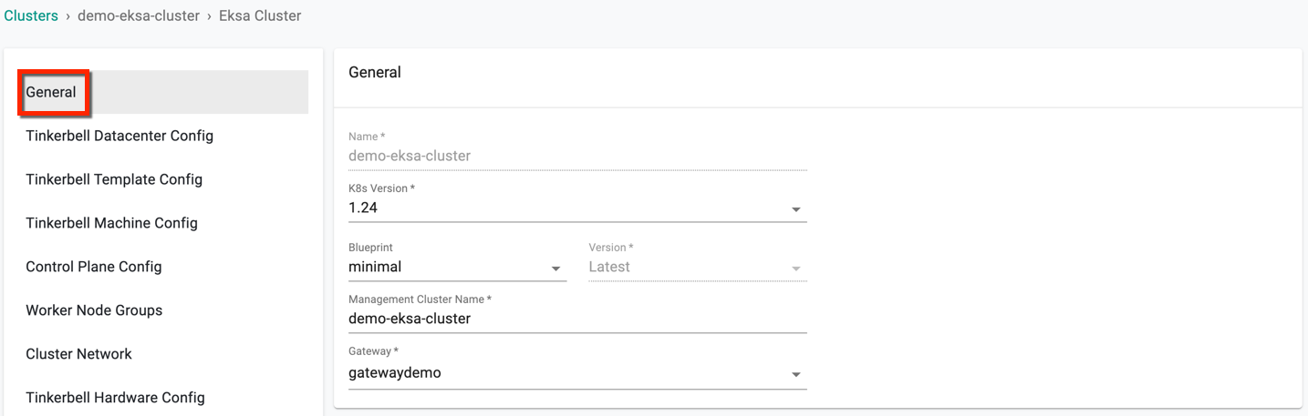
Step 1: General (Mandatory)
General section is mandatory to create a cluster
- Select a K8s version, where v1.24 being the latest
- Select a Blueprint and version. Customized blueprint can also be selected from the drop-down if required
- Edit the Management Cluster Name if required
- Select a Gateway from the drop-down
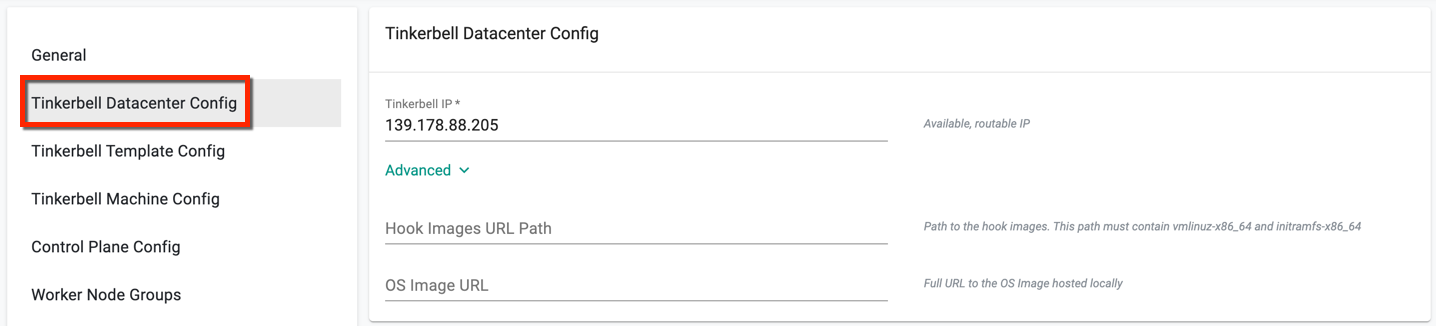
Step 2: Tinkerbell Datacenter Config (Mandatory)
Tinkerbell tool is used to automate the process of provisioning and configuration of machines part of the cluster. For more info on Tinkerbell, refer here
This section allows to customize the Tinkerbell Datacenter Config details
- Enter an available routable IP, which is unique and not consumed by any other machine(s)
- If not using the Amazon public repo, optionally click Advanced to provide the Path to the hook images and the full OS image URL
Step 3: Tinkerbell Template Configuration (Mandatory)
Users must create template for both control plane and worker node machines. Below is an example of template created for control plane machine
- Click Add Template Config and enter a template name
- Tinketbell ip is populated from the above configuration by default
- To provide the Gateway IP, click the Gateway IPs button and select one from the same network of Tinkerbell IP. For example, having Tinkerbell IP as
149.108.68.145, the Gateway IP must be similar to149.108.68.xxx - Select an OS. bottlerocket is selected by default
- Select a platform. equinix is selected by default
-
To assign IP addresses to nodes, choose between two IP Allocation Type: dhcp or static, depending on your requirements
- With static allocation, the same IP address is consistently assigned to each node
- dhcp allocation automatically assigns IP addresses to nodes using the dhcp service
-
Release Bundle, K8s version (latest version), and Network Interface Name is entered by default
- Click Create Template
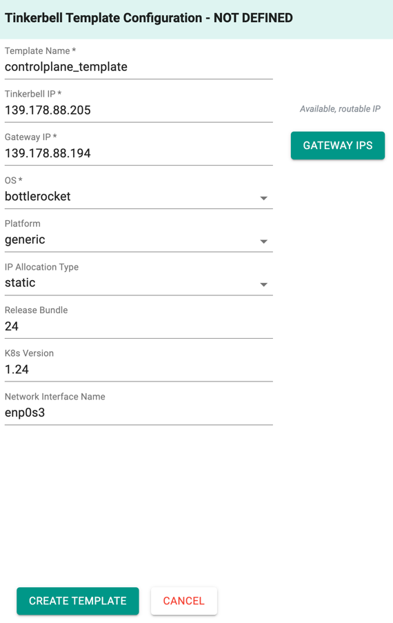
This will create a config template with the basic configuration details as shown below
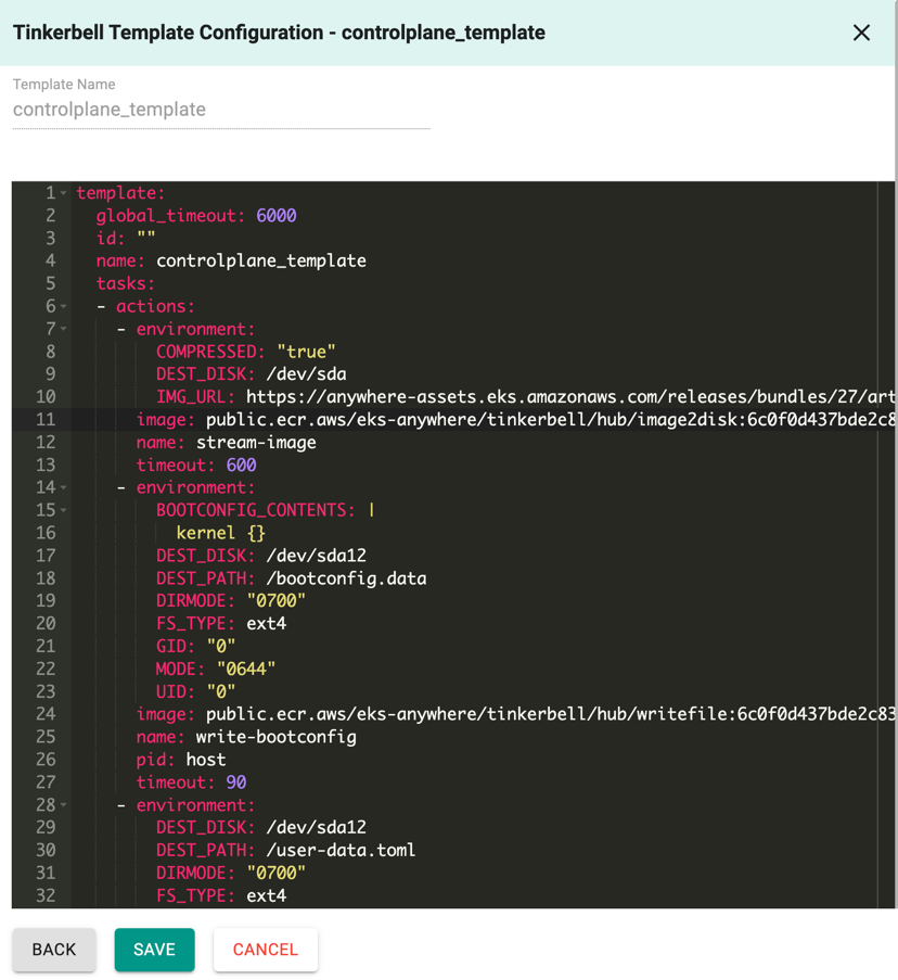
- Click Save
Similarly, create another template for worker node with the same information. If multiple worker node(s) are required, create template(s) for each worker node. To create a single node cluster, creating one template is sufficient.
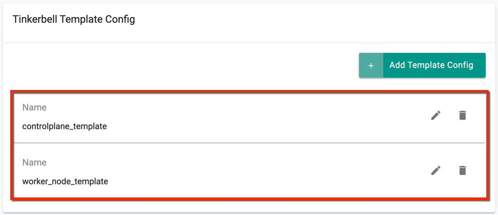
On successful creation, view the templates as shown below. Use the Edit icon to modify the config details or Delete icon to remove the template
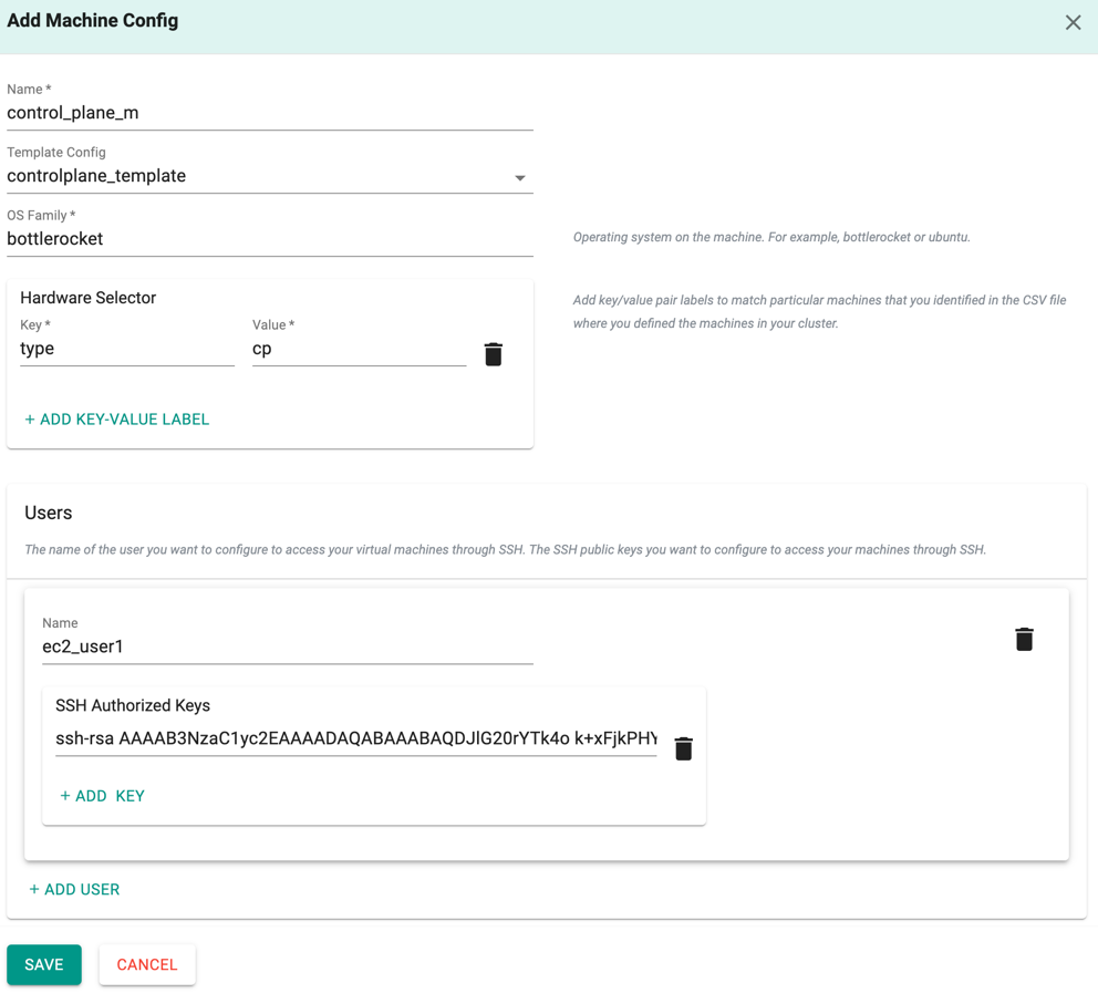
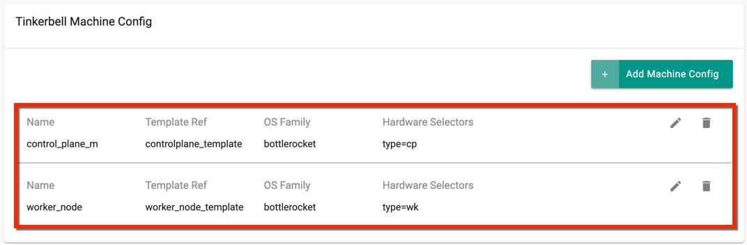
Step 4: Tinkerbell Machine Config (Mandatory)
Add the Machine config details:
- Click Add Machine Config and provide a name
- Select the respective template config from the dropdown. For example, for a control plane machine, select the template controleplane_template and for worker node machine, select the template worker_node_template, created in [Step 3](###Step3:TinkerbellTemplateConfiguration(Mandatory)
- Select an OS family. bottlerocket is selected by default
- Provide a key and value for the Hardware Selector
- Under Users, provide the machine user name and SSH Authorized Keys. Multiple users are allowed
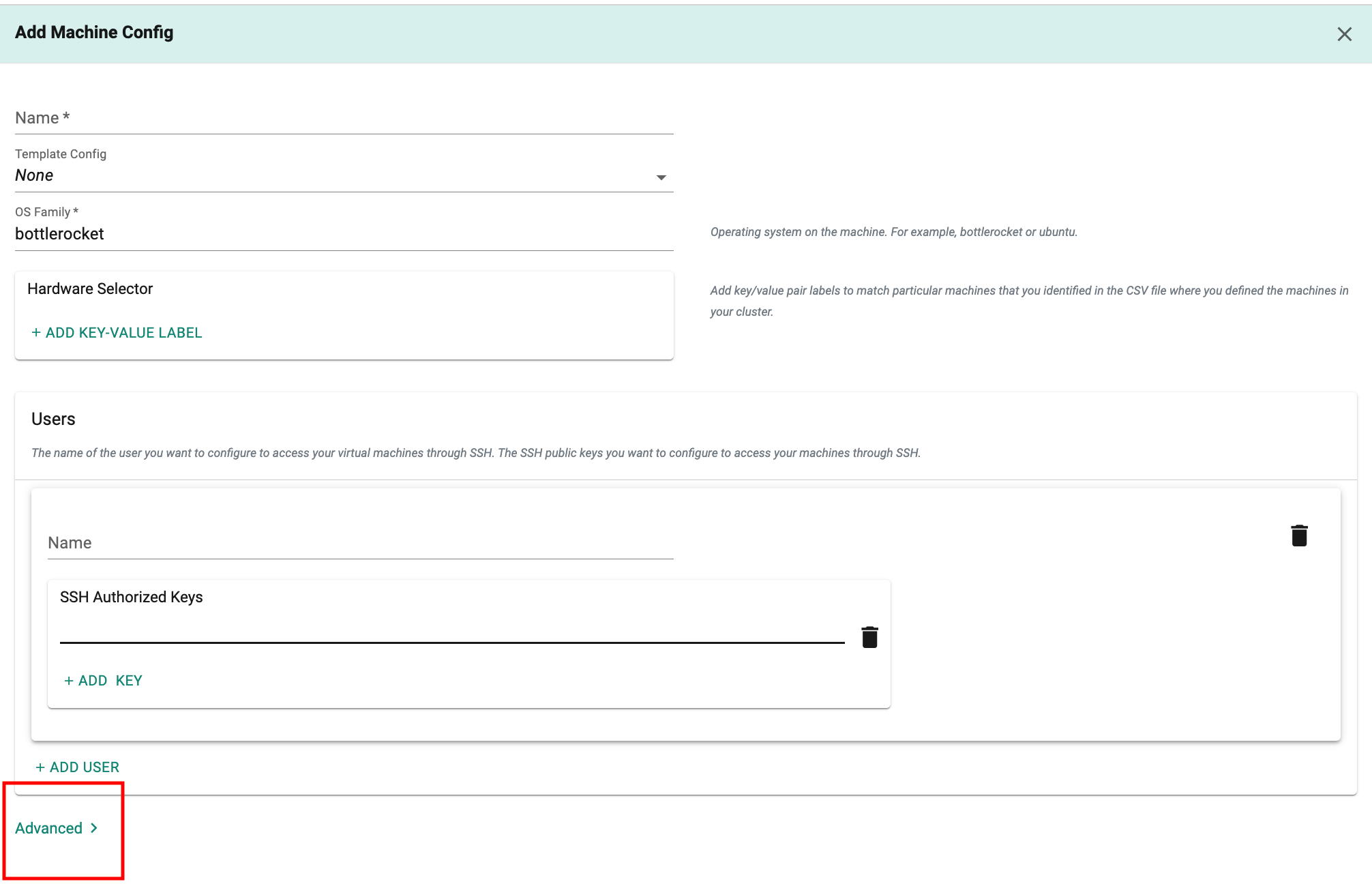
-
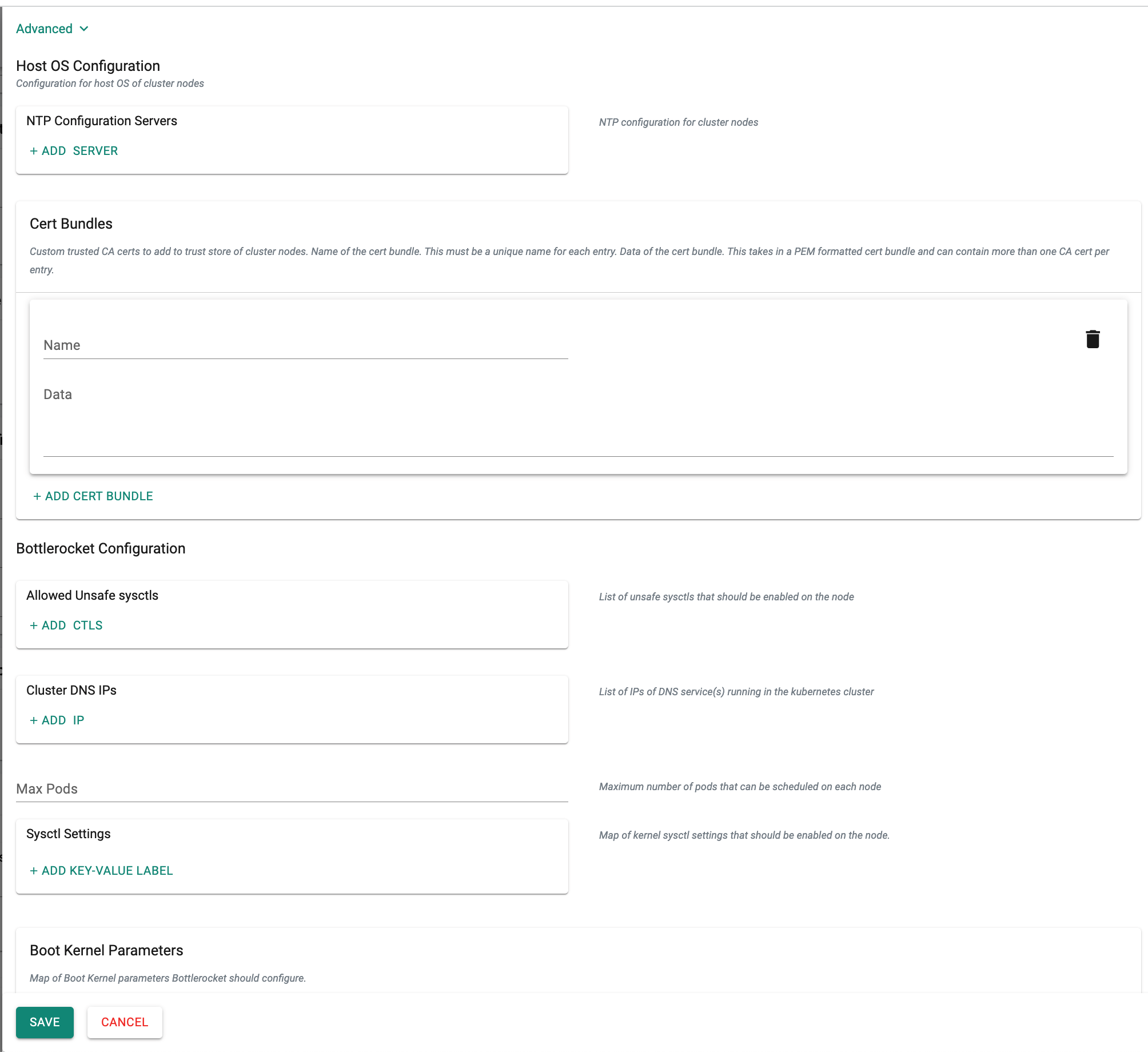
Within the optional advanced settings, users have the ability to include
Host OS Configurationdetails for the cluster nodes. This includes parameters such as NTP Configuration Servers, Cert Bundles, Sysctl Settings, and Boot Kernel Parameters specific to the host operating system. -
Click Save
Similarly, create another machine config for worker node. If multiple worker node(s) are available, create machine config for each worker node. For a single node cluster, one machine config is sufficient.
On successful creation, view the config details as shown below. Use the Edit icon to modify the config details or Delete icon to remove the machine config
Step 5: Control Plane Config (Mandatory)
- Enter the number of control plane machines
- Provide a control plane endpoint host. This IP address will be the IP address of your Kubernetes API server, but it should not already be in use on your network
- Select the Control Plane Machine Config, created in [Step4](###Step4:TinkerbellMachineConfig(Mandatory)
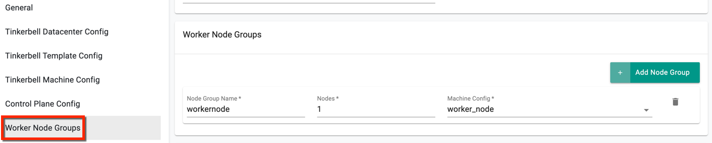
Step 6: Worker Node Groups
- Enter the Node Group Name and provide the number of worker node machine
- Select the Worker Node Machine Config, created in [Step4](###Step4:TinkerbellMachineConfig(Mandatory)
If there are more than one worker node(s), add node group(s) accordingly with the respective Machine Config details. Ignore this setting when a machine acts as both the control plane and worker node
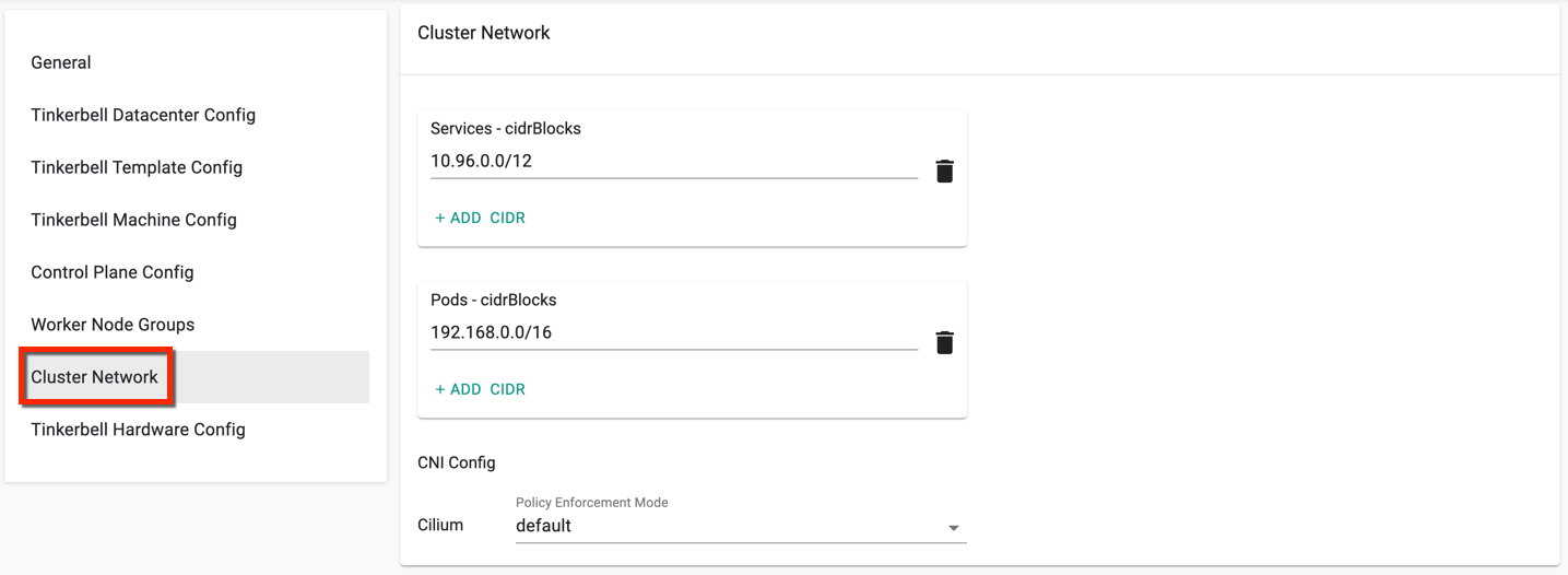
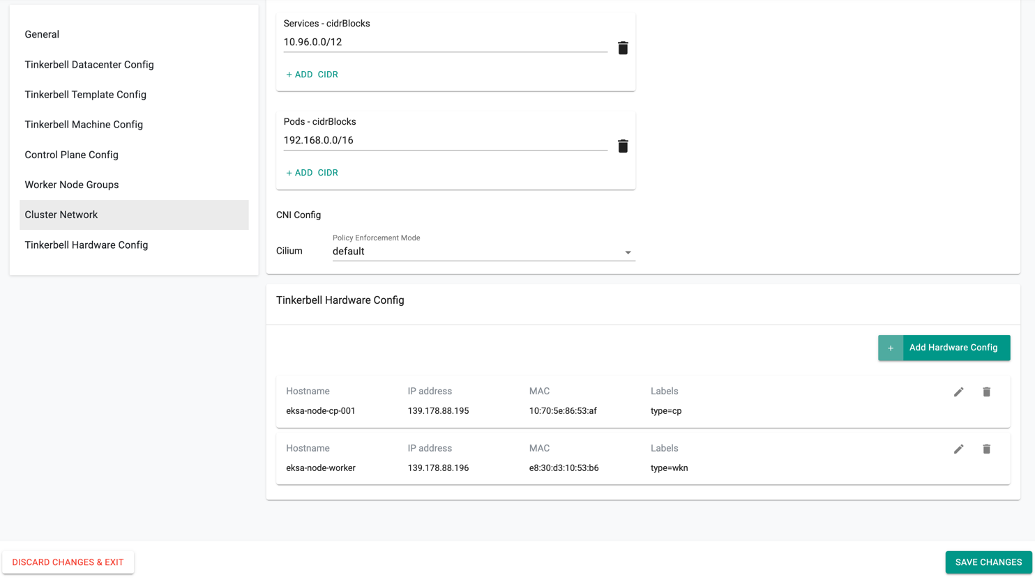
Step 7: Cluster Network
- In Cluster Network Settings, cidrBlocks for services and pods are provided by default
- Select the required Policy Enforcement mode for Cilium CNI Config
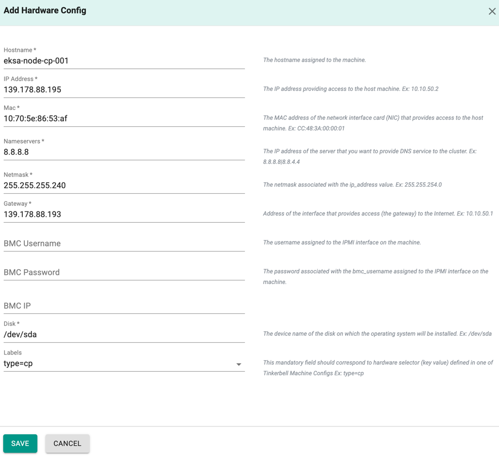
Step 8: Tinkerbell Hardware Config
Provide the Hardware (Control Plane and Worker Node machines) details here:
- Enter the hostname of the control plane machine
- Provide the IP address, Mac ID, Nameservers, Netmask, Gateway, Disk, and labels for the control plane machine.
- Optionally, configure BMC details of IPMI interface on the machine
- Click Save
Similarly, you can create the worker node hardware config by specifying the worker node machine details. Below is an example of both control plane and worker node hardware config
- Once all the information are provided, click Save Changes
- Click Provision
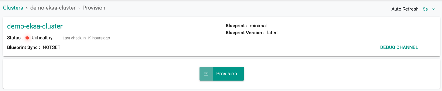
The cluster provisioning process is initiated. This installs the providers related configuration on K8s cluster, EKSA Baremetal provider management components, etc.
Inspect the hints displayed in the show debug output of the condition Clusters Spec Applied that will indicate to the users when it is time to restart the node.
- You must reboot the control plane and worker node machines once the new workload cluster creation begin and shows the Machine status as Pending as shown in the below image
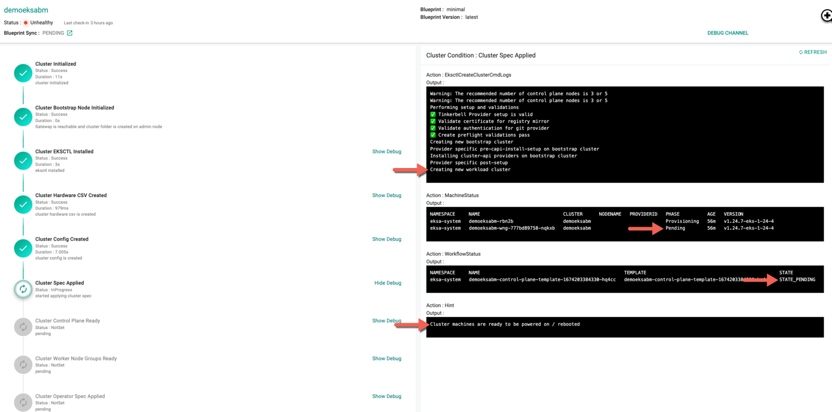
Note: During provisioning and scaling, users may have to manually restart, power on/off nodes if certain infrastructure providers do not support power management protocols.
- On rebooting the control plane/worker node(s) in Equinix, the custom OS Custom iPXE is booted on these machines. During cluster provision, Equinix supports sending unique iPXE scripts, enabling the users to manually install a specific operating system.
Use the Show Debug option to view the provisioning logs. The cluster provisioning approximately takes 40 minutes.
Successful Provisioning
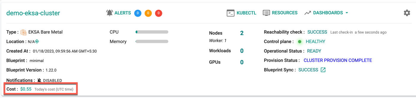
Once all the steps are complete, the cluster is successfully provisioned as per the specified configuration. Users can now view and manage the EKSA Cluster in the specified Project in the Controller. On successfully provisioning, the user can view the dashboards
To view the cost details of this cluster, click on the available cost link. This will navigate you to the Cost Explorer page, where you can access detailed cost information for this specific cluster.
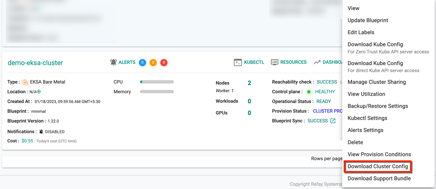
Download Config
Administrators can download the EKSA Baremetal configuration either from the console or using the RCTL CLI
Failed Provisioning
Cluster provisioning can fail if the user had misconfigured the cluster configuration (e.g. connectivity issues between the machine and controller). When this occurs, the user is presented with an intuitive error message. Users are allowed to edit the configuration and retry provisioning